Network Monitoring (Probing) Two Devices
The device can be configured to monitor the quality of the network path (network quality monitoring - NQM) between it and other AudioCodes devices. The path monitoring is done by sending packets from a "sender" device to a "responder" device and then calculating the round-trip time (RTT), packet loss (PL), and jitter. Since both responder and sender nodes are AudioCodes devices, the monitoring is done by sending RTP/RTCP packets in a way that accurately predicts the WAN service-level agreement (SLA) granted for real VoIP calls by the network.
If the packets sent mimic a G.711 or G.729 stream, the following quality measurements are also done:
|
●
|
Listener quality MOS per ITU-T specification |
|
●
|
Conversation quality MOS per ITU-T specification |
You can configure up to 10 network quality probing paths. For example, you can configure three probing paths, where your device is configured as a sender for three different responder devices, as shown in the figure below:
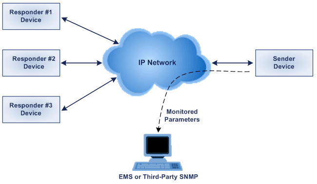
You can periodically poll the device for the latest VoIP quality metrics and specify thresholds for the quality metrics mentioned above. If these thresholds are crossed, the device generates the following SNMP traps to AudioCodes One Voice Operations Center (OVOC) or third-party SNMP-based manager:
|
■
|
NqmConnectivityAlarm: Connectivity with monitored probe destination is lost |
|
■
|
NqmRttAlarm: High RTP detected toward probe destination |
|
■
|
NqmJitterAlarm: High jitter detected toward probe destination |
|
■
|
NqmPacketLossAlarm: High packet loss detected toward probe destination |
This feature is configured using the CLI. Below is a list of some of the CLI commands. For a full list and description of the related CLI commands, refer to the CLI Reference Guide.
|
■
|
nqm responder-table – adds a responder (IP address and port) |
|
■
|
nqm probing-table – defines the polling attributes (duration and frequency) |
|
■
|
nqm sender-table - adds a sender (including RTT, PL, and jitter thresholds; associates probing definition; responder address; local interface) |
The following procedure describes how to quickly configure network quality probing.
|
➢
|
To configure network quality probing: |
|
1.
|
Configure the "sender termination" side: |
|
a.
|
Bind a WAN interface to the NQM service: |
(config-system) bind GigabitEthernet 0/0 nqm
The chosen WAN interface should be the interface on which the NQM packets are planned to flow bi-directionally and binding is necessary to create the corresponding static NAT rules. If the NQM session is planned to flow within the LAN then no binding is needed and this step can be skipped.
|
b.
|
Configure a row in the Probing table: |
(config-system)# nqm probing-table 0
(probing-table-0)# set probe-name voip_probe_1 ; identifies this line
(probing-table-0)# set start-time now ; starting time of this probe
(probing-table-0)# exit ; activates the probe
|
c.
|
Configure a row in the Sender table to define a sender termination: |
(config-system)# nqm sender-table 0
(sender-table-0)# set sender-name main_office_voip_checker_1 ; identifies specific sender
(sender-table-0)# set target-ip 10.4.3.98 ; IP address of responder termination
(sender-table-0)# set target-port 3900 ; listening port number at responder termination
A responder termination defined by the pair <target IP address, target port> can be defined only once for a single sender line; multipile senders can’t be defined to send packets to the same responder termination.
(sender-table-0)# set probe-name voip_probe_1 ; name of probing row previously configured to be used by this sender
A single row in the Probing table may be shared by several senders, thereby sharing and simplifying common attributes.
(sender-table-0)# set source-interface-name NQM_WAN ; name of network interface to send packets from
If you want to output packets to the WAN interface, simply set NQM_WAN as the source interface name; otherwise, set the interface name to a specific interface name.
(sender-table-0)# exit ; activates the sender line
|
2.
|
Configure the "responder termination" side: |
|
a.
|
Bind a WAN interface to the NQM service: |
(config-system) bind GigabitEthernet 0/0 nqm
The chosen WAN interface should be the interface on which the NQM packets are planned to flow bi-directionally and binding is necessary to create the corresponding static NAT rules. If the NQM session is planned to flow within the LAN then no binding is needed and this step can be skipped.
|
b.
|
Configure a row in the Responder table: |
(config-system)# nqm responder-table 0
(responder-table-0)# set responder-name vmain_office_voip_responder_1 ; name tag to identify this line
(responder-table-0)# set local-port 3900 ; listening port number at responder termination
(responder-table-0)# exit ; activates the probe line
Ensure that the local-port value is the same as the target-port value set for the corresponding sender termination.
(responder-table-0)# set source-interface-name NQM_WAN ; name of network interface to send packets from
|
●
|
If you want to listen to the WAN interface, simply set NQM_WAN as the source interface name; otherwise, set the interface name to a specific interface name. |
|
●
|
Ensure that the network interface the responder termination is listening upon is in-sync with the target-ip value set for the corresponding sender termination. |
(responder-table-0)# exit ; activates the responder line
|
■
|
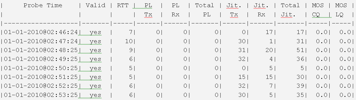
On the sender termination device, type the following command to view eight result rows of sender "0": |
# show system nqm 0 8